My Homemade Solar Water Heater
There are many reasons to heat your household water with solar power. The obvious reasons include a desire to reduce environmental pollution, save money on your electric bill, and impress your neighbors. But there are other not-so-obvious reasons as well, such as “hey, a project involving solar power!” and “I wonder how inexpensively I can make this thing?” It was with these thoughts in mind that I decided to build my own solar water heater.
After weighing the pros and cons of different designs, I finally settled on this one:
There are three primary functions performed on domestic water by all solar water heaters, namely heating, transporting, and storing the heat from the sun. This design also provides additional functions, which include measuring, controlling, recording, and reporting the temperatures.
This is a so-called split system, which means that the liquid that circulates through the heating panels (more on that later) never mixes with the water going into the house. The theory of operation for this type of system is simple – a liquid in the panels is heated by the sun and is pumped through the heat exchanger, where it transfers its heat to the domestic water. Let’s take it step by step:
The sun heats the roof-mounted solar collector panels (1), through which circulates a non-toxic antifreeze. The controller (2) senses that the temperature of the collector array exceeds that of the water in the bottom of the modified electric water heater (3) and turns on the pump (4). The pump, with the assistance of the header tank (5), pumps the hot liquid from the solar collectors down to the heat exchanger (6), which transfers the heat from the liquid to the water, causing its temperature to rise. The cooled liquid then returns to the solar collectors to be reheated. A solar photovoltaic panel (7) keeps the battery (8) charged so that it can power the controller and pump. The heated water rises to the top of the modified water heater and is fed to the intake of the existing home water heater (9) to replenish hot water that is used by the occupants of the house.
I like this design because the entire solar water system is located upstream of the existing water heater, supplementing instead of replacing it. This means that my old water heater will continue to operate the same way it always has if necessary.
I will describe each part of the system, and explain details of its construction. Individual components were purchased, scrounged, repurposed, fabricated, or a combination of these methods. A primary design goal was to keep costs to a minimum, so I am listing my costs associated with each item.
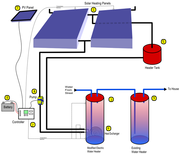
Of course, you can’t have a solar water heater without some way for the sun to heat your water. The solar collectors that I used were commercially manufactured from aluminum, glass, and copper. I’m sure I could have made some panels from scratch, but the ones that I’m using are very good quality and I found a bargain on them (or so I thought) that I just couldn’t pass up.
Whilst browsing on www.alibaba.com, I came across a solar water heater collector manufacturer in China (GuangZhou JOHO New Energy Co.,Ltd) that didn’t insist that purchases be made in large quantities. In fact, their minimum purchase quantity is one. Their top-of-the-line model was only $235, and it boasted a 97% efficiency rating. A comparable collector here in the USA would easily cost four or five times that – how could I pass up a deal like that?
Well folks, remember the old saw “If it’s too good to be true…”? Here’s the final cost breakdown:
Two collectors: $470 Packaging: $45 Shipping: $250 Wire Transfer Fee: $75 Middle Bank Charge: $30 Transport Company “Handling Charge”: $65 "Dock Fee”: $10 "Truck Cleaning Fee”: $2 Homeland Security Inspection Fee: $35 Repacking Fee (after inspection): $25 ------- Total Cost: $1,012.00
I guess I still came out ahead of where I would be had I bought the collectors locally, but it was quite a hassle. I guess if I had it to do over again, I’d still do it this way – I just wouldn’t fret over it so much.
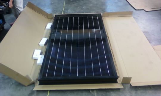
Figure 1: One of the two solar collector panels from China.
Since the solar collectors came without any kind of mounting brackets, I had to make my own. To prevent rust and galvanic corrosion, I used aluminum and stainless steel exclusively for the mounting brackets. The extruded frame of the collectors was manufactured with two channels along its length, which was just right for the heads of some stainless steel bolts that I had. The rest of the frame was fabricated from 1” square aluminum tubing and U-channel.
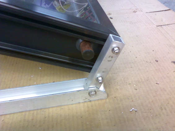
Figure 2: Details of the solar collector mounting frame construction.
Ideally, the solar collector panels would be exactly perpendicular to the sun at all times for maximum efficiency. As a practical matter, however, that’s only going to be the case for a few seconds each day. I ran calculations, used solar angle calculators I found on the web, and measured the angle of the sun at noon during the vernal equinox (Really! I did!). But none of that was really necessary, because the best angle to use was simply my latitude, about 35.5 degrees. Mounting the collectors at this angle, facing due south, was the optimum position, at least in the summer time. I made the mounting brackets in such a way that I can adjust the angle without too much trouble, just so I can experiment with different settings this winter.
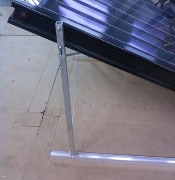
Figure 3: Details of the collector mounting frame.
After subtracting the slope of the roof where I planned to locate the solar collectors, I cut some one inch square aluminum tubing and bolted it inside a length of 1-1/4” U-channel. I then bolted the tubing to the extruded channels in the collector. A couple of aluminum braces on the high side made the whole unit very sturdy and easy to mount on the roof of my garage.
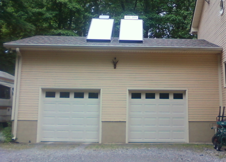
Figure 4: Solar collectors in their operating position.
The vertical distance between my water heater and the top of the solar collector array is approximately 15 feet. I was surprised to find out how much power it would take to pump a liquid that far – it seemed impossible to find a pump that would generate enough pressure to pump it that high while running only on a few watts of power from a photovoltaic panel. Yet I knew it was possible, because I had seen other solar water heaters do it. I finally realized that I only needed enough pressure to overcome the distance from the pooling level of the liquid to the top of the solar collector array, and I can set the pooling level to whatever level I want!
When the pump is off, all of the antifreeze drains out of the collector panels, and settles at some point in the pipes below the panels. This point is the pooling level. Since there’s as much natural pressure on both sides of the lowest point (i.e., the heat exchanger), the pump only has to move the antifreeze from the pooling level to the highest point in the loop, which is the top of the collector panels. This is about 5 feet in my case, an easy push for the pump.
Like I said, when the pump switches off, all of the antifreeze drains from the panels. This antifreeze has to go somewhere! The purpose of the header tank, located in the attic just below the collector panels, is to give the antifreeze somewhere to go. When the pump is running, the header tank should be nearly empty. When the pump stops, the level of the antifreeze in the header tank should increase by the amount of antifreeze in the panels.
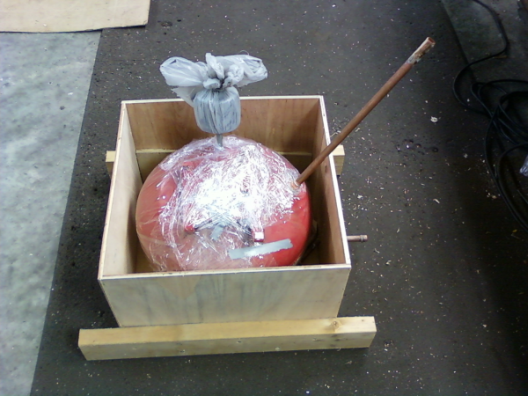
Figure 5: An old air compressor tank makes a great header tank.
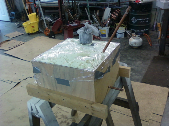
Figure 6: "Good Stuff" expanding foam should insulate the header tank very well.
I used a small “pancake” type air compressor tank for my header tank. After attaching all of the plumbing and wrapping it in cellophane, I placed it into a plywood box which I subsequently filled with expanding foam insulation. To keep an air bubble from hindering the flow of the antifreeze, I added a cheap screw-on automotive oil filter to the top to let air in and out of the tank without allowing insects to do the same.
Speaking of letting air in and out, I need to point out one thing that the original design didn’t take into account. Since nature abhors a vacuum, you can’t just expect the antifreeze to drain from the panels unless it is replaced by something else, namely air. To allow the antifreeze to drain from the panels properly, I added a couple of L-shaped pipes to the highest point on each panel, and stuffed them with some copper wool from a dish scrubber. That let air into the panels without allowing bugs and rain to get into the system. I didn’t have to worry about the antifreeze escaping through these vents, since the pressure at the top of the loop is essentially zero.
I needed a pump that met the following specifications:
Requires no more than about 10 watts of power at 12 volts
Is able to withstand heat up to at least 300 degrees or so
Not adversely affected by the propylene glycol antifreeze
Pump at least 100 gallons per hour
Inexpensive
As it turns out, these specifications are not easily met! I was able to find a pump on eBay that met all but the “inexpensive” spec, which I guess is pretty subjective anyway. The pump I wound up with is an automotive auxiliary cooling pump made by a German manufacturer called Pierburg. It’s used in Audi and BMW cars so I guess it’s pretty tough. The motor and pump are magnetically coupled, so there’s no seal to wear out. I was, however, able to ruin one by accidently running it dry. At about $85 apiece (eBay price – I don’t even want to know the dealer price) you don’t want to do that very often.
The storage tank for the hot water is a modified 50 gallon electric water heater from Lowe’s. I bought the cheapest one that they had (about $286) because all I really needed was the tank itself. The only real modification is the replacement of the lower electric heating element with the solar heat exchanger. Having the output of this tank feed the input of the existing water heater works great, because any solar heating, regardless of how small, will help lower my electric bill. Also, if we have a string of cloudy days, the old water heater still operates just as it always has.
The heat exchanger is the heart of the entire system. It takes the hot antifreeze from the solar collectors and transfers the heat to the household water in the tank. It occurred to me that I can avoid drilling holes in the new water heater tank by having the heat exchanger input and output lines pass through the existing hole for the lower heating element. This was no easy task, since the hole is only 1¼ inches in diameter. The upper heating element was left in place, but is not used.
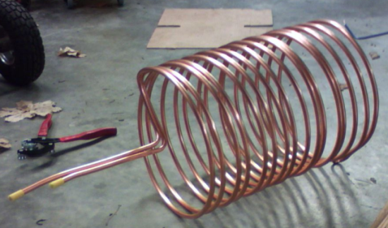
Figure 7: The heat exchanger. Yes, this entire unit will fit through a 1¼” hole!
After trying several different ways to make the heat exchanger, I finally settled on one that consists of 50 feet of ¼” ID copper tubing, folded in half and wrapped around a five gallon bucket. This was the perfect size for lying in the bottom of the water tank, and that size of copper tubing was pretty cheap – only about $22 as I recall. The hard part was folding the tubing in half without kinking it. I tried several ways of doing it before successfully bending it tightly enough to pass through the heater element opening in the tank. It’s not pretty, and it’s definitely a little narrower in the bend, but it works!
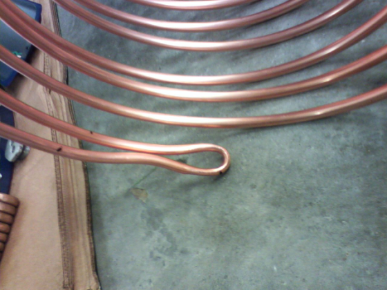
Figure 8: As long as it doesn't kink, it will work!
Winding the heat exchanger coil in this manner allowed me to kind of “screw” it into the water heater tank and leave both ends protruding through the heater element hole.
To seal the heater element hole, I cut the plug from the original electric heater element that came with the water heater, drilled the holes out where the element passed through it, and slid it over the end of the heat exchanger. It was a very tight fit, so I had to really work it to slide it into position.
I still needed to make it watertight, and of course any time you have two dissimilar metals in contact with one another there’s a chance of galvanic corrosion. I consulted with some experts at the welding supply store, and we decided that brazing the copper pipe to both sides of the steel plug with a special (read: expensive) silver-bearing brazing rod would be the best choice. That seems to have been a good decision, because it hasn’t leaked a drop since I put it all together.
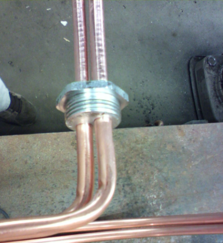
Figure 9: Assembling the heat exchanger entry/exit port.
Installing the heat exchanger into the water heater was a matter of inserting the folded end into the hole, and then rotating it clockwise. Because of the elasticity of the coil, I found that it was easier to get into place by laying the water heater tank on its back first. I also found that removing the sacrificial anode, which is an aluminum rod that extends down into the tank from the top to help reduce corrosion, made insertion a lot easier. I replaced the sacrificial anode after getting the heat exchanger in place and standing the tank back up.
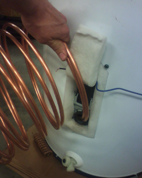
Figure 10: Inserting the heat exchanger into the tank.
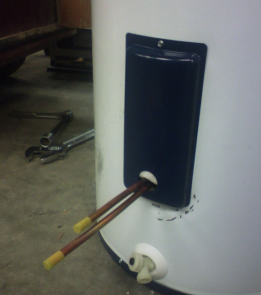
Figure 11: Tip - cut a hole in the element cover for the heat exchanger tubes.
I made the controller from scratch, because doing that sort of thing is one of my favorite hobbies. The basic design is that of an Arduino (Atmel ATMEGA) processor with an RS232 interface and Dallas Semiconductor One-Wire temperature sensors. I needed to add a display of some kind, and this seemed a good place to use some of those 8x8 LED arrays that I had bought from eBay a while back. Although the 8x8 LED array works great, however, I will probably redesign it to use an LCD display sometime in the future, for power saving reasons.
I drew the schematic with the excellent (and free!) TinyCad schematic capture program, and created the printed circuit board with the equally excellent (and free!) FreePCB printed circuit design program. Once I got everything just right, I sent the design to BatchPCB.com, who combines small boards from other folks like me into larger batches and has them made by a PCB foundry in China. It takes a while to get the boards made that way, but it is much cheaper because you get to share the setup costs with the other folks that have boards in the batch. Total cost for 2 boards was $57.
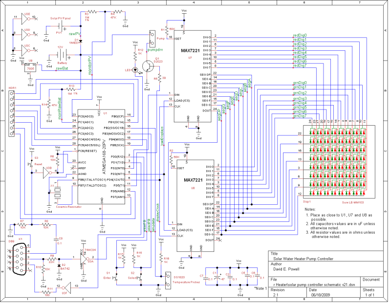
Figure 12: Controller schematic
The controller monitors the temperature at various points in the system and turns the pump on or off at the appropriate times. It also reports the system status via the LED display and the serial port. This last feature allows me to show the status of the system on my web site, along with graphs of historical temperature and voltage data.
Temperatures are measured at the heat exchanger input and output, the tank top and bottom, and both collector panels, using Dallas Semiconductor DS18S20 temperature probes. The battery and photovoltaic panel voltages are measured by two of the analog inputs to the processor, using simple resistive voltage dividers to scale the voltages down to a level that can be handled by the processor. The pump is switched on and off by saturating the base of a small power transistor.
If I ever redesign this controller, I’ll probably replace the LED matrix with a cheap liquid crystal display. The matrix is pretty cool, but it uses a lot of power and the resolution is quite limiting when trying to display data. Furthermore, the MAX7221 multiplexer chips that drive the matrix are very expensive. I was able to get a couple as free samples, but if I had had to pay for them they definitely wouldn’t have been part of the design.
The microcontroller that I used for the solar controller is the ATMEGA328 manufactured by Atmel. Fortunately, there is a large hobbyist group growing around this processor, thanks to the incredibly flexible and easy to use Arduino platform. One of the many Arduino variations that have sprung up that uses this processor is the Dorkboard, manufactured and sold by Wulfden at Hawk’s Mountain. This fun and inexpensive little board was the base from which the design for my solar controller was created.
Of course, any project that uses a microprocessor or microcontroller requires programming, and this is no exception. The Arduino platform uses a subset of the C programming language, and has lots of user written libraries to perform various tasks. The program for the solar controller is much too long to show here, but can be downloaded.
Power for the controller and the pump is supplied by a 12 volt gel cell battery, along with four 5 watt solar photovoltaic (PV) panels. The PV panels charge the battery and supply a little extra “push” for the pump during the active time of the day. It would have been cheaper to just use a small wall-wart type of power supply instead of the PV panels and battery, but that would have gone against the very spirit of the whole solar concept. Besides, I had some PV panels lying around that I had bought on eBay a while back that needed to be put to use!
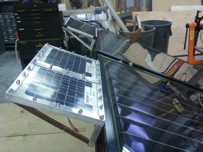
Figure 13: PV panel brackets
I started with only three solar panels, but they just weren’t able to keep up with the current draw required by the system. Over a period of about a week, the average battery voltage would slowly drop from the nominal 12 volts down to about half that. I purchased another 5 watt panel from Harbor Freight Tools when it was on sale for about $30, and adding it along with the others will hopefully fix that problem.
I made brackets for the panels from 1” aluminum angle stock. They attach to the top of the solar collectors in the same manner as the collector mounting brackets. Once again, all hardware is either aluminum or stainless steel.
Installing the system was mostly just plain old plumbing. I put some plumber’s putty underneath the mounting brackets for the solar collectors where the bolts pierce the roof, and a large steel washer on each bolt on the inside of the attic to spread the wind load. Where the tubing goes through the roof, I took a short piece of ¾” copper pipe, cut it lengthwise, and flattened it with a hammer. I then drilled a ½” hole in it for the pipe to pass through and soldered it to the pipe. This made an excellent piece of flashing around the pipe to keep rain from sneaking into the garage around the edges of the pipe. A similar arrangement, in the shape of an inverted “J”, made a neat weather head for the wiring.
Half-inch copper pipe was run between the heat exchanger, pump, header tank, and roof. I insulated all of it with standard foam pipe insulation. One day I may replace the insulation with something thicker, because I don’t think that this insulation is really working as well as I would like.
I attached the copper pipe to the solar collectors where it exits the roof with standard ¾” automotive heater hose. This allowed me the flexibility to “fine tune” the solar collector mounting angle without having to modify the plumbing.
One problem that I encountered involved a large air bubble in one of the pipes. This pipe originates at the bottom of the header tank, travels across the rafters to the wall, then makes a 90 degree turn to go down to the heat exchanger. I had unknowingly placed the 90 degree turn a little higher than the bottom of the header tank, which meant that any air trapped inside the pipe had no place to go. Once I got all of the air out of the pipe everything started working fine, but I really should fix the slope of that pipe.
There was one other problem, involving noise from the pump. I attached the runs of pipe to and from the pump, as well as the pump itself, to the wall for sturdiness. Although this made the whole structure very sturdy and tight, it made the wall a great (but unwanted) sounding board for the pump. The kitchen is on the other side of the wall, and the constant whirr of the pump motor was driving my wife insane. Detaching everything from the wall fixed the noise problem, but now it is all just kind of hanging in midair. I have yet to come up with a good solution for that problem. The pump by itself is practically silent, but it seems that any contact between the wall and the pump or pipe allows the noise to return.
So far, this system has worked even better than my expectations. It has been operating since mid-July, and supplies most of the hot water for our needs. It was actually working too well for a while during the summer, heating the water to over 160 degrees at times! I revised the microcontroller program to turn off the pump if the water gets that hot – those temperatures are just too dangerous for domestic hot water. I’m anxious to see how well it works this winter and if it needs to be adjusted for the winter sun or not.